JFD-2010S Multi channel digital partial discharge detector
1. Executive standards
The performance index of all components in the system are in accordance with the following standards regulations
| GB/T16927.1-2011 | High-voltage test techniques Part 1: General definitions and test requirements. |
| GB/T16927.2-2013 | High-voltage test techniques Part 2:Measuring systems |
| GB/T7354-2003 | Partial discharge measurements |
| DL/T 846.4-2004 | General technical specifications for high voltage test equipment Part 4: Partial discharge detector |
| JB/T 7586-1994 | Partial discharge detector in discharge calibrator |
The other items meet the technical requirements, technical documents and technical agreements of the users.
2. Equipment name
| Serial number name |
Product name | Product model |
Quantity | Comment |
| 1 | Multi-channel digital partial discharge detector |
JFD-2010 | 1 | System test host |
| 1.1 | Multi-channel digital partial discharge detection software |
JFD-2010-S | 1 |
|
| 2 | Correcting pulse generator | JZF | 1 | Choose according to sample matching, multi match on model |
| 3 | Input unit | 2 | Choose according to sample matching, multi match on model |
|
| 4 | partial discharge filter adapter | PDLF-1 | 2 |
|
| 5 | System accessories (cable length can be customized according to customer requirements) | 1 set | Standard 8m discharge signal line, 2; adapter line, 2; high frequency line, 1; power line, 1 fuse 2 | |
PS:According to the requirements, the calibration certificate of partial discharge tester and calibration pulse generator can be provided and the third party testing institution is national |
||||
3. Introduction of equipment
(1) JFD-2010S Multi channel digital partial discharge detector
This detector is suitable for partial discharge detection and online monitoring of transformers, mutual inductor, generators, arresters, bushings, GIS, capacitors, power cables, switches and other high voltage electrical equipment with various voltage levels and capacities.
Product structure:
- Display: 15 inches true color TFT LCD display, industrial level brightness; display resolution: 1024 x 768; 4 digit display voltage value
- External interfaces: USB interfaces; power supply interfaces; 2 signal input port; grounding terminal; external synchronous signal input terminal; RJ45 interface; RS232 interface
- Size: long*wide*height(540×460×320)mm
- Weight: 18kg
Main technical target:
- Measurement channel: independent 2 channel (non channel conversion).
- The capacitance range of the tested product: 6pF~250 F.
- Detection sensitivity: 0.01pC.
- Sampling accuracy: 12bit; sampling rate: 20M / S.
- Display work method:
Display method: ellipse—sine—lineTrigger synchronization mode:internal and external trigger mode, internal trigger for instrument power synchronous trigger, 50Hz; external trigger for synchronous test power supply frequency, 50~400Hz arbitrary frequency. - Time window: the size of the phase is randomly selected. The time window can be dynamically enlarged and the two time windows can be opened at the same time or separately.
- Filter band: 3dB low frequency fL has three stage: 10, 20 and 40 Hz; 3dB high frequency fH also has three stage: 80, 200 and 300 kHz. fL and fH can flexibly form all kinds of filter pass.
- Signal amplifier
Amplifier response to asymmetry of positive and negative polarity:<1dB。Gain adjustment:Divided into coarse and fine gain. Coarse gain divided into 5 files, 20dB gain difference between grade (10 times), error ±1dB, gain tuning range of >20dB. - Partial discharge signal measurement: can measure the partial discharge signal in continuous, magnifying way error ±5% (full scale meter)
- With data storage, playback function, with printing function and can generate standard test report.
- Working temperature: -10~45℃,relative humidity:≤95%.
- power supply AC220V;frequency 50Hz;power 300W.
Description of product features:
- Independent four channel digital partial discharge measurement. Synchronous sampling, processing and display;
- Inside and outside Synchronous random selection, with zero mark indication and phase resolution function;
- Display mode:Randomly choose three display method: ellipse, straight line and sin;
- Waveform analysis of single discharge pulse in order to determine discharge characteristics;
- The test data and waveform can be saved at any time, and the test records which have been saved in the past can be re displayed and analyzed;
- Gain range: each channel is individually adjusted, and the waveform display can be adjusted at any time without affecting the measurement results;
- The special or random waveform can be captured and analyzed in a single way;
- Anti-static interference function can remove the phase fixed interference signal;
- Correlation filtering technology can effectively remove the random interference which is not synchronized with the power supply;
- The bandpass filter adopts analog and digital hybrid filtering technology and the bandwidth can be randomly assembled to effectively suppress all kinds of interference;
- Arbitrary phase window, single window, double window optional, 360 degrees arbitrary choice of free window;;
- It can monitor the test voltage while detecting partial discharge;
- The discharge measurement, time and waveform analysis of partial discharge pulse are carried out;
- 2D and 3D partial discharge spectra display;
- Storage and print partial discharge graph and data automatically, and generate test report automatically;
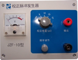
(2) Pulse correction generator
Polarity: positive and negative alternation
Repetition rate: 1.2kHz
Frequency range:>±100Hz
Pulse rising edge time:<60nS
Pulse falling edge time:>100uS
Error correction charge Eq=(Eu2+Ec2)1/2 ≤±5%
Size:160×125×50mm3(different model, same size)
Weight:0.5kg
Battery:6F22 9V

There are many choices for output discharge according to different pulse correction generator. Specific as follows:
| Model | Selection of output discharge gear |
| JZF-10 | 5PC、10pC、20pC、50PC |
| JZF-9 | 5PC、10pC、50pC、500PC |
| JZF-9A | 10pC、20pC、50PC、100PC |
| JZF-6 | 10pC、20pC、50PC、100pC、200pC、500PC、1nC 、2nC、5nC |
| JZF-6D | 5pC、10pC、20PC、50pC、100pC、200PC、500PC、1nC |
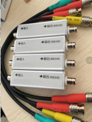
(3)Input unit
Input unit is the important unit to detect the discharge information from discharge experiment circuit, also be called detection impedance. This input unit can match the several partial discharge detection method (such as parallel method, series method and balance method) be recommended by IEC270, from No. 1 to No. 12 and 7R. The input unit uses a dual tuned input loop of high frequency transformer. The primary stage is the LCR loop, and the primary inductance is tuned in the amplifier band of the partial charge amplifier with the equivalent capacitance of the test circuit.

| Order number | Tuning capacitance range | pC (imbalance circuit) |
Permission RMS | |
| Imbalance circuit | Balance circuit |
|||
| 1 | 0~25~100pF | 0.02 | 30mA | 0.25A |
| 2 | 25~100~400pF | 0.04 | 50mA | 0.5A |
| 3 | 100~400~1500pF | 0.06 | 120mA | 1A |
| 4 | 400~1500~6000pF | 0.1 | 0.25A | 2A |
| 5 | 1500~6000~25000pF | 0.2 | 0.5A | 4A |
| 6 | 0.006~0.025~0.1uF | 0.3 | 1A | 8A |
| 7 | 0.025~0.1~0.4uF | 0.5 | 2A | 15A |
| 8 | 0.1~0.4~1.5uF | 1 | 4A | 30A |
| 9 | 0.4~1.5~6.0uF | 1.5 | 8A | 60A |
| 10 | 1.5~6.0~25uF | 2.5 | 15A | 120A |
| 11 | 6.0~25~60uF | 5 | 25A | 200A |
| 12 | 25~60~250uF | 10 | 50A | 300A |
| 13 | Resistance (for cable) | 0.5 | 2A | 15A |
(4) Partial discharge signal filter adapter
Model:PDLF-1
The adapter is connected between the input unit and the partial discharge detector, which is used to filter the high frequency interference components doped in the partial discharge signal. It can effectively improve the test result of field test and the signal to noise ratio of partial discharge. It is the best choose in field.
4. The service condition of complete set of equipment
- the service area altitude not to exceed 1000m.
- Ambient air temperature range is -25~+45℃
- The relative humidity of ambient air less than 80%RH
- Does not contain chemical corrosive gases and vapors
- No conductive dust and explosion hazard
- No severe vibration and shock
- Enter the front of the power supply system without leakage protector
- The system adopts no corona cable
- Indoor use

