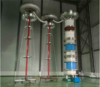
Resonant (Induced/Frequency) voltage test system

AC resonant test systems with variable inductance and module type are used for factory testing of medium and high voltage cables, power transformers, bushings, high voltage capacitors, generators, arresters and high voltage accessories. They include stackable modules that can be used to test a wide range of products. The systems can be expandable to cover future test requirements that may require higher voltage and power levels.
Features and Benefits
- Lowest PD noise level
- Low input power demand due to high quality factor
- Pure AC sine wave at output
- Multiple Q values to meet a variety of applications
- Highest voltages by cascading of several modules
- Large variety by single, series and parallel circuits
Applications
- AC withstand test on cables and cable accessories
- Applied voltage tests on transformers
- AC withstand tests on GIS, capacitors, generators and motors
- HV tests on voltage and current transformers
- Bushing testing
- Partial discharge testing
System Composition
Power of the test system is supplied through switchgear cabinet, voltageregulator and excitation transformer. If the reactor is metal tank type, theexcitation transformer can be built into the reactor. Power filter, which isinstalled at the low voltage side, is used for reducing power interference toguarantee low partial discharge for measurement background in the partialdischarge test.
Variable inductance reactor is the most important part of the variableinductance resonance test system. Inductance of the reactor is changed byadjusting the core distance, which is driven by a rare earth motor.
The high voltage filter is composed of two parts: isolation impedance andhigh voltage capacitor. The high voltage filter can be used to attenuate highfrequency interference and as the system basic load in partial dischargemeasurement
The control and measurement system includes: operating devices &industrial computer and instruments to measure voltage, partial discharge andcapacitance dielectric loss.
System Components
- Switchgearcabinet
- Regulator
- Excitertransformer
- Highvoltage adjustable reactor
- Highvoltage filter
- Powerfilter
- Controland measurement system (manual or automatic)
OptionalAccessories
- Isolationtransformer for control power supply
- Connectiondevices for series and parallel connection
- PD free HVcable
- Standardcapacitor
- Partialdischarge tester
- Air cushionchassis
- Otheraccessories that maybe necessary
Technical Parameters
| Model No. | Power | Maximum Output Voltage | Output Current |
| (kVA) | (kV) | (A) | |
| CLXZ-1050/350 | 1050 | 350 | 3 |
| CLXZ-3500/350 | 3500 | 350 | 10 |
| CLXZ-800/400 | 800 | 400 | 2 |
| CLXZ-1200/400 | 1200 | 400 | 3 |
| CLXZ-600/2*300 | 600 | 600 | 1 |
| CLXZ-1200/2*300 | 1200 | 600 | 2 |
| CLXZ-12000/2*300 | 12000 | 600 | 20 |
| CLXZ-21000/2*350 | 21000 | 700 | 30 |
| CLXZ-900/900 | 900 | 900 | 1 |
| CLXZ-3150/350*3 | 3150 | 1050 | 3 |
| CLXZ-3600/1200 | 3600 | 1200 | 3 |
| CLXZ-8000/1600 | 8000 | 1600 | 5 |
